Mô tả
 |
Crack Depth Meter
|
| Particularly precise measurement by means of a material characteristics curve with multipoint material correction |
|
| Leaflet |
|
| Determination of depth and orientation of surface cracks | |
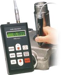
| Our new crack depth gauge RMG 4015 measures crack depths on workpieces of iron, ferrous and austenitic steels and can also be used for cracks in copper, brass, aluminium and other non-ferrous metals. For the measurement of oblique cracks a special oblique cracks probe is available. | |
| Measurement according to the potential probe principle | |
| A probe with four spring-loaded and gilded contact pins is positioned across the crack to be measured on the workpiece. A constant alternating current is passed via two of the pins into the workpiece; the two other pins measure the voltage drop across the crack, where the crack depth is derived from. The a.c. of the instrument utilizes the skin effect, which forces the current flow to the surface of the conductor and therefore follows the contour of the crack. The operation and measured value formation are monitored by the microprocessor of the gauge. Incorrect handling or faulty measurements caused by wrong attachment or imperfect contacts therefore are out of question. | |
| Measurement of oblique cracks | |
| In addition to common cracks running in most cases perpendicularly to the surface, the real life often shows oblique cracks, where usually it is not the expansion of the cracks which is of interest, but the oblique orientation and the projection with reference to the surface. If you know these measures it can be decided whether the post-treatment of a workpiece with cracks is technically possibly and economically reasonable. Therefore the instrument was equipped with an additional measuring function for the determination of oblique cracks, which permits to determine the inclination of the crack with respect to the material surface. | |
| The measurement is executed by means of an special four-pin probe, which permits to connect an external current pole which can be positioned left and alternatively right to the crack. Via the differences of the readings and the crack depth measured as well, the meter reliably will determine the inclination and the projection perpendicularly to the surface. Measurement is possible on all common magnetic and non-magnetic steels, with certain restrictions also on many non-iron metals. Thus the new pocket-sized instrument for crack measurement may be used universally for all types of naturally occurring cracks. |
 RMG 4015 with probe for measurement of oblique cracks |
| Interface for printing and connection to a PC | |
| Via the RS232 interface, test reports can be printed on small-sized printer (available as accessory) or the instrument can communicate with a PC. For this purpose, the PC program iCom is available, which not only acquires the measured values, but also offers data administration and graphical display. Furthermore, test reports or other documentations can be created. | |
| Physical Background of Crack Depth Measurement | |
| Crack depth determination with the potential probe method is based on the measurement of the electrical resistance between two points on the surface of a metallic workpiece. | |
| If there is a crack between these two points, the electrical resistance is higher than for a crack-free surface. The resistance will grow with the unknown crack depth. In this new approach, a four-pole technique is used: |  Principle of crack depth measurement by the potential probe method Principle of crack depth measurement by the potential probe method |
| Two current poles Sl and S2 enforce a constant current through the workpiece. The voltage U is measured between the other two measurement poles Ml and M2 and it is proportional to the electrical resistance between them. Therefore, the voltage U depends, in a characteristic manner, upon the unknown crack depth h, the known distances of the measurement poles 2a and the current poles 2s, and the electrical and magnetic properties of the material. In case of alternating current (AC), the skin-effect shifts the electrical field and the current lines towards regions just below the surface. Also, the current density is increased. The following formula gives the penetration depth in terms of the frequency and the material properties. |
|
| The higher the frequency, the more severe is this effect, i.e. the current will flow along the crack faces. As for a wire with reduced cross-section, an increase of the resistance is observed. |  Influencing parameters |
| For direct current (DC), no skin effect occurs and the current follows the path of lowest resistance, which corresponds to the shortest geometrical distance.For a precise crack depth determination with low measuring currents, AC has to be used. Low currents will avoid burnt contact spots to protect the surface of the workpiece and the current poles. Furthermore, the power consumption in case of battery operation will be drastically reduced.
Because the skin effect increases the voltage drop across the crack, the effective current path between the poles can be reduced with respect to conventional instruments. Smaller, more practicable probes can therefore be used and provide high resolution and accuracy. Even materials with high electrical conductivity, e.g. high-grade steels or Aluminium, can now be measured. |
|
| Disadvantages of Conventional Instruments | |
| The relation between the crack depth h and the measured voltage and the frequency is non-linear and is also dependent on the different electrical and magnetic properties. It differs from material to material and this fact is only inadequately considered in conventional instruments. As the measured voltages are extremely small (a few µV only), conventional instruments are very sensitive to interferences. Very often, the cable position influences the measurements by inducing voltages. In addition to this, uncontrolled contact problems occur, when the probe is attached on the surface. Wear of the probe tips can lead to unpredictable results. Measurements with conventional three-pole probes and separate current pole introduce additional errors, because the distance of the current pole is not taken into consideration. | |
| New Probes for the Crack Depth Measurement | |
| The new probes made by KARL DEUTSCH are generally equipped with four poles. Four decades of experience and continuous development in crack depth gauging have led to our most recent patent: DE3828552C2! | |
| A straight probe and an angled version are available. The straight-type probe has a square-shaped arrangement of the contact pins which therefore allows for measurement on very small or strongly curved surfaces. |  Linear and square arrangement of current (S) and measurement (M) poles |
| In contrast to the linear pole configuration with the current poles outside, the probe has to be placed in such a manner that the crack is in the center of both, measurement and current poles. In this case, the voltage drop, is measured a few millimeters besides the current path. Current and measuring poles consist of spring-loaded, tip-hardened and gilded contact pins. They guarantee optimum electrical contact and require low attachment pressure only. |  Straight crack depth probe |
| The angled probe has a prism-shaped attachment area which ensures that the contact pins are pressed onto the surface by their spring-force only. Similar pressure is obtained for each pin during the measurement providing reliable results. The prismatic shape of the attachment area makes positioning on curved surfaces (e.g. pipes) easier. The angled probe can also be positioned on the inner surfaces of pipes or other hard-accessible workpiece areas. |  Angled crack depth probe |
| The contact pins can be exchanged without tools: when worn, they are pulled out of the guiding sleeve of the probe and replaced by new ones. The probes themselves are maintenance-free. For rough or oxidized surfaces, self-twisting contact pins are the optimum solution: they turn around their axes, when pressed against the surface. Thus, a thin, non- or poorly conducting layer will be punctured for a safe contact with the conductive base material. |  Exchangeable and gilded contact pins with insertion tool |
| The built-in electronic circuitry inside the probe contains a preamplifier. Thus, the measured signal is safely transferred to the instrument. Furthermore, a memory unit is built into the probe. It stores the individual probe data and the material characteristics. |  Integrated electronic circuitry: preamplifier and characteristics memory |
| Use of the RMG 4015 | |
| A reference block with an artificial crack with a crack depth starting from zero up to 10 mm is provided with the RMG 4015. Therefore, the user can check the instrument and probe calibration during the tests. Deviations caused by worn probe pins or extreme temperatures can be compensated by re-calibration. The corrected values are then stored in the probe memory.
The conversion of the measured voltages into crack depths is done by the microprocessor which controls the RMG 4015. Factory-set calibration tables are stored in the instrument for this purpose. Prior to a measurement, the probe is placed on a crack-free spot of the workpiece. The measured voltage is compared with the stored values of the calibration table. The individual characteristics of the material are found and used by the microprocessor to determine the exact crack depth in the subsequent measurement. The measurement itself is supervised by the microprocessor. Illegal operation due to inadequate pole contact, wrong attachment or shaking of the probe is avoided. Therefore, false results are nearly impossible. Optimum reproducibility of the measurements (+/- 0.1 mm for 100mm crack depth) are obtained. Even steels with low or no permeability (e.g. Austenite) or non-ferrous metals of higher electrical conductivity (e.g. Aluminium or brass), which are more difficult to test, can be measured with sufficient accuracy. |
|
| Technical Details of the RMG 4015 | |
| The current through the workpiece is, similar to other conventional instruments, 500 mA. But in contrast to the existing devices where the current flows continuously as long as the probe is attached, the current is a pulse of a few milliseconds duration for one measurement. The repetition rate allows approximately one measurement per second. The display is updated accordingly. Therefore, the battery-operated instrument can measure for up to 12 hours with permanently attached probe. In case of rechargeable batteries, the instrument does not have to be opened. The batteries can be recharged while in the instrument by means of an external charger unit.
The foil keyboard consists of push buttons, permitting a direct access to the basic measuring functions of the instrument. More parameters may be displayed with the menu key. The parameters are shown in clear language (English or German possible). Therefore, the operation is as simple and easy as with conventional Wall or Coating Thickness Gauges. The data logger of the instrument can handle up to 3850 measurements, which can be stored in up to 300 separate batches. A built-in real-time clock automatically records date and time of a measurement. The measurements can be printed via an serial interface. The same interface also permits communication with a PC. For this purpose, the WINDOWS-based program iCom is available. It allows not only the transfer, but also the handling and graphic display of the measured values. Besides this, test reports and other kinds of documentation can be provided. The crack depth measurement using the potential probe principle, up to now accompanied by many uncertainties, is converted into a reliable and user-friendly measuring method by the RMG 4015. The reduction to pocket size, the simple operation of the probes, the easy-to-use program and the low price make the RMG 4015 a low-cost, simple and reliable test instrument. It is a useful supplement of the magnetic particle examination and penetration testing. It is always recommended when, for bigger or expensive workpieces, a reworking is needed, or when crack growth (e.g. in production lines) has to be monitored. NEW: From now and without extra charge all RMG 4015 come with a multipoint material correction function. This new feature permits the customer to acquire an individual material characteristics curve (which exactly meets the specimen under test and permanently is stored in the device), simply by creating test pieces, which only need to be fitted with saw cuts of different depth. Up to now, such “special characteristics curve” could be programmed into the device only by the manufacturer. From now, the multipoint material correction function allows for reliable measurements also with those materials which were judged to be “difficult” due to their unusual magnetic and electrical qualities. On request, older devices can be retrofitted with the new multipoint material correction function during a QM recurring test. |
|
| Ordering information | |
| Crack Depth Meter RMG 4015 incl. batteries | 4015.003 |
| Probes (incl. 1 set of replacement standard contact pins) | |
| Crack Depth Probe RMSL 0° | 4416.001 |
| Crack Depth Probe RMSL 90° | 4417.001 |
| Crack Depth Probe RMSQ 0° | 4418.001 |
| Crack Depth Probe RMSL-S 0° incl. contact magnet with cable | 4421.001 |
| Crack Depth Probe RMSL-S 90° incl. contact magnet with cable | 4420.001 |
| Special characteristics curve for RMG probe | 4901.001 |
| Accessory | |
| RMG reference block (crack depth = 0..10 mm) | 4720.002 |
| Charger unit (230 V) for RMG 4015 | 2806.001 |
| Battery set NiMH, 2 x 1.2 V (size AA, capacity > 2000 mAh) | 6015.001 |
| Charger unit, 230 V, for NiCd/NiMH batteries (4 x AA) | 1465.661 |
| Mobile Thermo Printer, battery-powered, incl. charher unit (230 V) | 6010.201 |
| PC and printer cable (RMG – printer + PC) | 1657.307 |
| Fitting tool for RMG probe pins 4815.00x | 4816.001 |
| Protection bag for RMG 4015 | 4825.001 |
| Adapter cable USB->RS232 incl. drivers CD | 2691.001 |
| Software | 1868.003 |
| iCom, PC software for Windows XP(SP3) / 2000 / Vista / 7 | 2906.001 |
| Consumption Material | |
| Set of 8 contact pins (standard) | 4815.001 |
| Set of 4 contact pins (needle) | 4815.002 |
| Set of 8 contact pins (self-twisting) | 4815.003 |
| Polishing vleece for reference block (set w/ 5 pcs) | 4820.001 |


Đánh giá
Chưa có đánh giá nào.